This is the general design for the IO systems used by the DWMC-16.
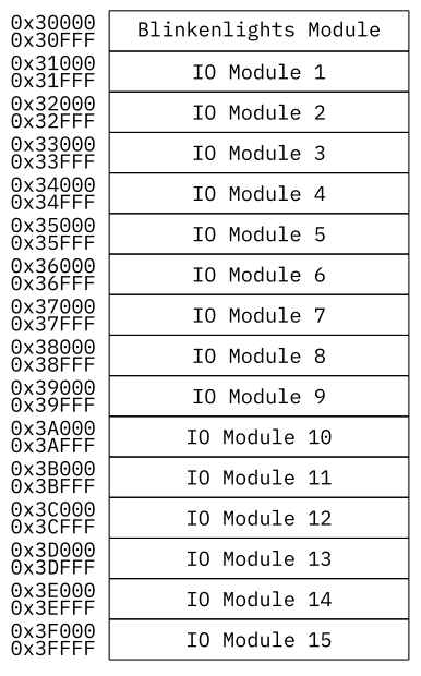
As the IO System is mapped into a sector in memory, it does share the same subdivision into 4 kiWord memory blocks, with each block of memory used to address one IO module.
These 4 kiWord memory Blocks are going to be take n up by the IO modules control and data registers, as well as a ROM, containing information about the IO Module, as well as code to address the module based on a Main OS/Monitor API.
The modules types are going to be separated into the following types:
- Serial IO
- Parallel IO
- Mass Storage
- Timers
- Others
Special APIs are going to exist for the first four types, while special drivers for other module types will have to be provided either in the modules ROM or external programs.
It will also be possible to use higher memory pages, sectors and blocks to allow the system to access larger, for example, the frame buffer or a graphical output module.
Blinkenlights Module
A special module within the IO system is the Blinkenlights Module, which will be part of the system from the start and which will be an integral part of both the Monitor and the Main OS. The Module is located in the first block of the Memory Mapped IO sector, populating the addresses from 0x30000 to 0x30fff.
Functionally, the Blinkenlights module will display the address, data and some control bus activity on a set of LEDs, as well as control some of the buses. It will contain switches and buttons to reset the system, to switch between single step and normal operation, and use it to write to the buses and through them modify memory on a low level.
Additionally, the Blinkenlights module will contain two additional displays, in form of a ten digit 7-segment LED display and a 2×20 character LCD or VFD. This is supplemented by a 20 key hexadecimal keyboard with control keys.
Possible Implementation
Generally, all momentary push buttons/keys used for the Blinkenlights Module are going to be Digitast style buttons, while all LEDs will be red.
While the logic used for the buttons, to connect to the bus is up for the later design phase, the 7-segment LED display with the hexadecimal keypad are going to be taken care of by an Intel 8279 keyboard and display controller.
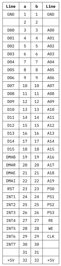
Bus Connector Layout
For the bus connector layout of the DWMC-16, standard DIN 41612 32 column a+b connectors are going to be used for the general availability of these Eurocard connectors, as well as back planes using this standard.